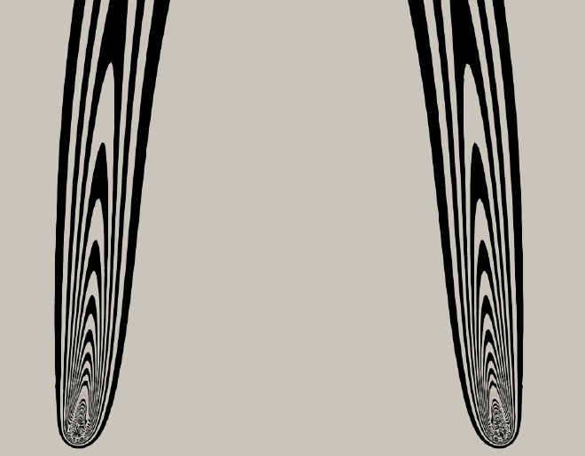
Fig 212. Interaction of two equal laminar plumes
Table of Content
“Electrically heated nichrome wires 18cm long and 7.2cm apart form plumes as in figure 203, which merge by entrainment of the air between” Photograph by Pera & Gebhart
The lead visualization compares a simulation result with the experimental photograph taken by Pera & Gebhart (1975). Despite visual differences, the simulation captures the main plume behaviour. Minor 3D effects and the local influence of wire the supports that are visible in the photograph are not captured by the simulation’s idealized 2D representation of the 18 cm long, 0.25 mm diameter nichrome wires. Furthermore, as noted by Pera & Gebhart, even very small disturbances in the laboratory can have significant effects on these relatively weak plume flows. With these sensitivities considered, the simulation successfully reproduces the core processes of plume interaction and is in good agreement with the experimental findings.
Introduction #
The fluid motion caused by density differences brought on by temperature changes, known as natural convection, can cause various interesting flow phenomena. The thermal plume rising from a localized heat source is a well-known example. But what happens when several of these plumes appear near each other? The complex flow patterns resulting from the ensuing interaction differ greatly from those of an isolated plume. This raises the question: What process determines their interaction with one another, and what effects do variables like heat input have on this behaviour?
This post investigates the dynamics of two interacting laminar thermal plumes. The experimental findings of Pera & Gebhart (1975) are replicated and the physics of the observed phenomena is explained, paying special attention to the concept of entrainment; the process by which a fluid flow (like the thermal plumes) attracts ambient fluid from its surroundings.
Mechanism of plume interaction #
A rising thermal plume is not an isolated entity. It continuously absorbs and combines with the ambient fluid around it. The dynamics of the plume depend on this process. The warm, less dense fluid in the plume’s core that moves upward shears on the surrounding cooler fluid. As the cooler fluid accelerates upwards, mass balance requires the cooler fluid to also advect into the plume.
Two adjacent plumes then have to compete for the ambient fluid in the area between them. When they are positioned closely together, a region of relatively low pressure forms between the plumes as a result of this mutual “tugging” on the inbetween fluid. As a result, the plumes are pulled toward one another. This explains the distinctive deflection and subsequent merging that is observed. The plume strength (heat input) contributes to how strong this effect is.
Observed plume dynamics #
In accordance with Pera & Gebhart’s experiments, the baseline simulation is run with a heat input of Q = 20000 W/m². To observe the fully developed plume interaction, the transient simulation is run until t = 6.7 seconds. During this transient simulation, we observe three distinct phases that clearly illustrate the interaction process. These phases are illustrated in the figures below, which show the resulting temperature fields displayed as isotherms.
- Initial Phase: After the heat sources are activated, two separate plumes form directly above the heat sources. Their interaction is at this point minimal. This initial state of two separate columns of rising air serves as the baseline from which the interaction will develop.
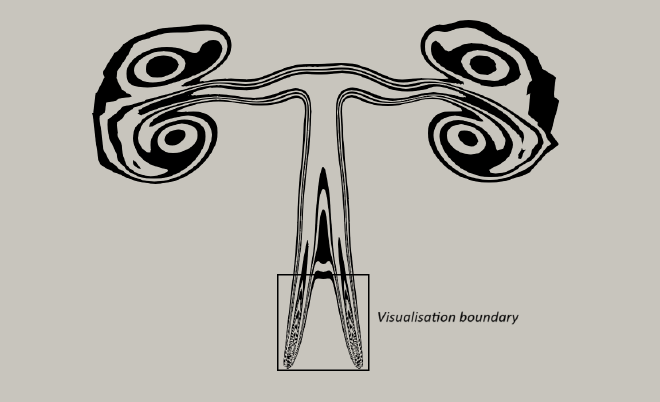
- Deflection due to Entrainment: The entrainment mechanism and the resulting low-pressure zone between the plumes cause ambient air to be pulled inwards between the plumes. The higher ambient pressure on their outer edges causes the plumes to deflect towards one another quickly after they are first formed. The figure below visualizes this process in detail. The white streamlines show how the air is drawn towards the blue, low-pressure regions. The suction, or entrainment of air from the space between the plumes creates a force that pushes them toward each other.
- Merging Zone & Combined Plume: As the plumes approach one another and their isotherms combine, they eventually create a single, broader combined plume further downstream. This combined structure is not permanently stable; far downstream, it becomes unstable and evolves into a more complex pattern. A small amount of air is pushed outward when the plumes meet each other, this is due to the sudden change in air velocity at the point of collision, which causes a temporary high pressure area. The figure below shows the plumes combining, and the resulting puff of air to the sides.
Effect of Varying Heat Input #
To explore the dynamics of plume interaction, simulations are conducted for various heat input values (Q) while keeping the wire separation (7.2cm), domain size (1x1m), and fluid properties constant. At t = 5 seconds, the temperature fields are contrasted for varying values of Q. The figures below represent 200, 2000, 40000 and 80000 W/m² respectively.
Observations: The simulations demonstrate a strong and consistent dependence of the plume characteristics on the applied heat flux. This is in line with the basic concepts of natural convection, which state that the Richardson number (Ri) and Grashof number (Gr) dictate the system behavior. These dimensionless numbers represent the ratio between the buoyancy force and inertial, respectively viscous, force. The buoyancy force scales with the temperature difference of the plume center and the ambient, which rises with increasing Q. Details on the Richardson and Grashof number are provided in the post of Figure 204.
The impact of varying heat flux on plume characteristics can be summarized as follows:
Plume strength and structure: There is a visible pattern in which increasing heat flux (Q) results in stronger, more well-defined, and “stiffer” thermal plumes, this can be noticed at the heat fluxes of 40000W/m² and 80000W/m². For 200W/m² and 2000W/m² it is noted that the plumes are weak, diffuse, and have trouble forming a clear vertical structure.
Interaction dynamics (deflection and Merging): Somewhat surprisingly, the plumes deflect inwards towards one another at lower altitudes as the heat flux decreases. At higher heat fluxes, the increased buoyancy causes plumes to develop more upward momentum whereby they better resist the coalescing effect of the entrainment, causing higher vertical ascent and delayed merging. At lower heat fluxes, the merging of the plumes into a single, combined structure takes place much closer to the heat sources. The plumes almost instantly merge upon formation at the lowest Q values.
Computational model #
The above simulations are carried out in COMSOL Multiphysics. The incompressible Navier-Stokes equations in conjunction with the Boussinesq approximation and the energy transport equation control the flow. The full derivation can be found in Figure 204. In summary: the Boussinesq approximation is used to model the flow-temperature coupling that causes buoyancy. The approximation manifests itself as a temperature dependent body force in the Navier-Stokes momentum balance equations, and is valid when temperature differences are not very large.
The continuity equation (mass conservation), momentum equation (incorporating the Boussinesq approximation) and energy transport equation (in terms of temperature) are: $$ \nabla \cdot \mathbf{u} = 0 $$ $$ \rho_0 \left( \frac{\partial \mathbf{u}}{\partial t} + (\mathbf{u} \cdot \nabla)\mathbf{u} \right) = - \nabla p + \mu_0 \nabla^2 \mathbf{u} + \rho_0 \mathbf{g} \beta (T - T_0) $$ $$ \rho_0 c_p \left( \frac{\partial T}{\partial t} + \mathbf{u} \cdot \nabla T \right) = \nabla \cdot (k \nabla T) + Q_{\mathrm{source_term}} $$
Where:
- \(\mathbf{u}\) - velocity vector [m/s]
- \(p\) - pressure [Pa]
- \(T\) - temperature [K]
- \(\rho_0\) - reference density at reference temperature \(T_0\) [kg/m³] (1.204 kg/m³)
- \(\mu_0\) - reference dynamic viscosity at reference temperature \(T_0\) [Pa·s] (1.81 x 10⁻⁵ Pa·s)
- \(\mathbf{g}\) - gravitational acceleration vector [m/s²] ( 9.81 m/s²)
- \(\beta\) - thermal expansion coefficient (\( 1/T_0 \) for an ideal gas) [1/K] (0.00341 K⁻¹ )
- \(c_p\) - specific heat capacity at constant pressure [J/(kg·K)] (1005 J/(kg·K))
- \(k\) - thermal conductivity [W/(m·K)] (0.0257 W/(m·K))
- \(Q_{\mathrm{source_term}}\) - applied volumetric heat source [W/m³]. The input heat flux of 200 to 80,000 W/m² is converted to a volumetric source within the wire domains.
The 2D model consists of a rectangular 1x1m domain filled with air, featuring two circular boundaries acting as line heat sources with a constant heat input per unit length (Heat input varied between 200W/m² and 80000W/m², corresponding to approximately 0.15 W/m to 73 W/m for a 0.25mm wire diameter). The domain edges are defined as walls with no in or outflow, and an initial ambient temperature of 293.15K.
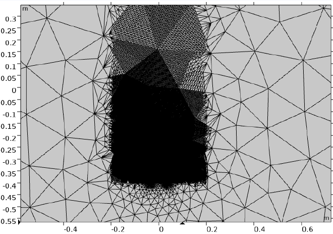
The computational domain is discretized with an unstructured triangular mesh created in COMSOL, as seen in the figure below. Heavy mesh re-refinement is applied away from the region of interest. This keeps the required computational resources reasonable while still permitting minor fluid motion far away from the wires. This proved important, as a too small box would lead to considerable ficticious flow circulation affecting the severity of the slopes of the plumes.
Conclusion and Relevance #
This CFD analysis of interacting laminar thermal plumes shows how neighboring buoyant flows are attracted to one another and eventually merge due to entrainment and the pressure gradients that result. The simulations offer important insights into the underlying physics and replicate the experimental findings of Pera & Gebhart. Higher heat inputs result in more coherent, vertically rising plumes that resist merging until further downstream, whereas lower heat inputs cause plumes to deflect inward and merge soon after formation. These findings have real-world applications in engineering and the environment, including modelling wildfires, designing cooling tower arrays, and smoke management systems.
References #
- Pera, L., & Gebhart, B. (1975). Laminar plume interactions. Journal of Fluid Mechanics, 68(2), 259-271.
- [COMSOL Multiphysics v. 6.x. COMSOL AB, Stockholm, Sweden.]