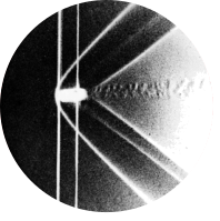
Fig 85. Trailing vortex from the tip of a rectangular wing
Table of Content
“At 12.5\(\degree\) angle of attack the vortex is seen to separate well ahead of the trailing edge. The wing has an NACA 0012 profile and aspect ratio 4. At this Reynolds number of 10,000 the wake is laminar, in contrast to the opposite page. Visualization is by colored fluid in water.” ONERA photograph, Werlé 1974
Vortex formation #
In figures 23 and 34 we looked at boundary layer theory and separation along the surface of an airfoil, the image above reveals a different type of flow phenomenon, which is the formation of a wing tip vortex.
What is a vortex #
A vortex is a region of rotating fluid motion, around a centreline which can either be straight or curved. Vortices are often the result of strong pressure differences between opposing sides of an object.
Wingtip vortices #
When an airfoil produces lift, the pressure is higher beneath the wing and lower above the wing, as shown in the figure below. For an infinitely long wing (or a wing between two plates like figures 23 and 34), these pressure fields do not interact. However, in a real three-dimensional flow with a finite-span wing, fluid near the tip can move laterally, curling around from the high-pressure region beneath the wing to the low-pressure region above, which creates a wingtip vortex that trails into the wake. These vortices persist far downstream and are clearly visible in figure 85.
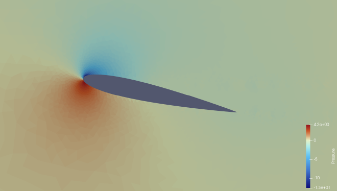
Wingtip vortices contribute to induced drag, which is drag due to the generation of lift. Compared to pressure drag caused by separation, induced drag is often more difficult to eliminate. Often winglets or higher aspect ratio designs are used to reduce vortex strength and limit this energy loss [1].
Simulation #
To replicate the original figure by H. Werlé in the ONERA water tunnel, the simulation was carried out using Star-CCM+.
Geometry #
The NACA 0012 airfoil geometry was imported from Airfoil Tools. In the original source, there were no dimensions given about the size of the water tunnel, but it did give the Reynolds number as \(Re_L = 10000\) and the length of the airfoil, which is \(0.1\ m\) [2]. The span of the wing is four times the chord, therefore the width of the airfoil is \(0.4\ m\). The inflow velocity is given by:
$$ \begin{gather*} Re_L = \frac{\rho v_{\infty} L}{\nu} = 10000 \\ v_{\infty} = \frac{10000 \cdot 8.8871\cdot{10}^{-4}}{997.561 \cdot 0.12} = 0.089\ m/s \end{gather*} $$
Mesh #
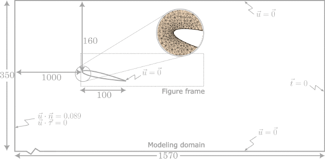
A 3D tetrahedral mesh was used because this figure includes vortices that can only occur in 3D. The base size was set to \(0.005\ m\), but a refinement was done at the wing tip by reducing the base to \(0.00125\ m\), which gave a total of 5117946 cells. 30 prism layers were used at a height of \(2.5/cdot 10^{-4} m\). Only half of the water tunnel was modelled to reduce computation time. One side was set to be a symmetry boundary condition and the other a no-slip wall. The top and bottom of the domain were also set to no-slip walls to simulate the walls of the water tunnel. The water tunnel was made to be double the width of the airfoil, so \(0.4\ m\) wide. The rest of the dimensions can be found in the figure below. The domain upstream was made extra long, so an animation could be made where random particles occur, instead of particles repeating at the same location.
The physics and visualisation were done in the same way as figure 23.
Inaccuracies in results #
Together with the factors mentioned at the end of the web post for figure 23. There are more factors at play when it comes to this figure. The geometry at the wing tip has a massive impact on how the vortices form. In this simulation, the side of the wing is vertical, but it could be rounded, which will give a very different vortex.
References #
[1] NASA Glenn Research Center. Winglets. NASA, 2023 URL: https://www1.grc.nasa.gov/beginners-guide-to-aeronautics/winglets/
[2] Werlé, H.. Le Tunnel hydrodynamique au service de la recherche aérospatiale. O.N.E.R.A 1974