Fig 253. Projectile at M=1.015
Table of Content
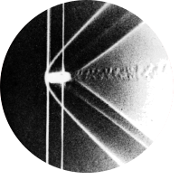
“The model artillery shell of figures 223 and 224 is shown here still earlier in its trajectory, when it is flying at a slightly supersonic speed. A detached bow wave precedes it, and the distant field is quite different, but the pattern near the body is almost identical to that shown in figure 224 for a slightly subsonic speed. This illustrates how the near field is ‘frozen’ as the free-stream Mach number passes through unity.” Photograph by A. C. Charters
Series #
This figure is part of a series together with figure 223 and figure 224, which illustrate the transition from subsonic to supersonic flow for the same type of artillery shell. The suggested reading order is:
- The current post first, which provides a heuristic exposition of different types of shockwaves.
- Figure 224, which addresses the conceptual challenge of simulating transonic flow.
- Figure 223, which discusses the two relevant modeling equations: the compressible Navier-Stokes equations and the Euler equations.
Shockwaves #
When an object travels through a medium at a speeds faster than the speed of sound in that medium (i.e., a speed higher than “Mach 1”), it generates shockwaves. This is demonstrated in the experiment photographed above. Such shockwaves occur because pressure changes in a medium can propagate no faster than the speed of sound, as sound waves themselves are pressure waves. As such disturbance in the flow behave differently in subsonic and supersonic conditions. In subsonic flow, particles ahead of the disturbance (e.g., a moving object) are ‘informed’ by pressure changes and move out of the way. In supersonic flow, particles do not have this forewarning as the disturbance travels too fast. Consequently, as the disturbance arrives, nanoscale molecular collisions occur.
In this post, the general properties of shockwaves are explained first. Next, the particular types of shockwaves observed in the above experiment, bow shock waves and lambda shock waves, are examined.
Properties #
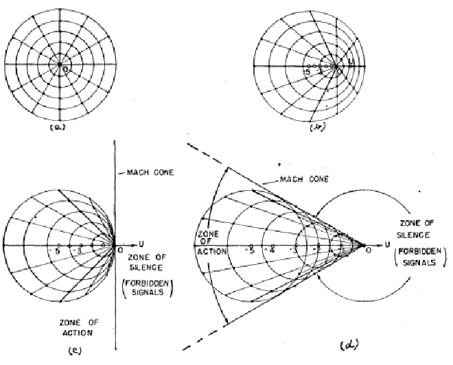
Shockwaves typically have an oblique shape, as observed with the shockwaves created by the artillery shell in the original experiment. When a body moves through a fluid at supersonic speed, it generates a pressure front that also moves at supersonic speed, pushing on the air. This pushing creates a high-pressure region, resulting in a very thin shockwave, approximately 200 nm thick. The angle of the shockwave around a particle is determined by the speed of sound, as the pressure signal relative to the particle travels in all directions at the sound velocity minus the relative flight velocity, as illustrated in the following figure:

This thin shockwave significantly impacts the downstream flow properties by increasing potential energy at the expense of kinetic energy. As a result, density, pressure, and temperature rise, while velocity decreases [2]. In this experiment, at low supersonic speeds, the flow transitions from supersonic to subsonic after passing through the shockwaves. Additionally, the direction of the flow stream is also altered by the shockwave, with the so called turning angle being determined by the velocity of the flow both upstream and downstream of the shockwave.
Bow shock waves #
The leading shockwave in the experiment is not oblique but is referred to as a detached shock or bow shock. This occurs because the turning angle through a shockwave is too small, preventing the fluid from moving out of the way, as is typical for a blunt body object [3]. The distance between the body and the detached shock is determined by the flow velocity and the shape of the body. Lower velocities reduce the turning angle and thus increase the distance between the detached shock and the body, as does a more blunt body [2]. At a greater radial distance from the object, the detached shockwave has a lower bending radius and becomes oblique.

Lambda shock waves #
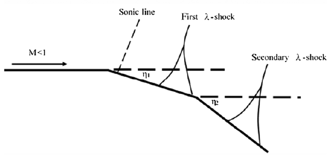
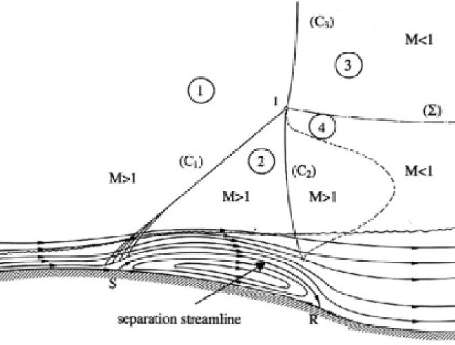
As mentioned, the relative fluid velocity in this experiment decelerates from supersonic to subsonic due to shockwaves. However, there is also acceleration around the convex corners of the artillery shell, bringing the velocity back to supersonic. At supersonic speeds, this acceleration around the corners results in a small expansion Prandtl-Meyer fan. The lower density in this region gives it a darker tint in the experiment image.


Simulation #
Domain #
Per the above descriptions, the exact shape and orientation of the shockwaves is highly dependent on the geometry of the traveling object. To accurately recreate the experiment in CFD, it is thus crucial to determine the correct shape of the artillery shell. The rough 2D shape of the axisymmetric domain was created by tracing over the experimantal photographs. Additional details were then added based on the observed shock and expansion waves. For instance, a small increase in diameter at the middle of the shell was included based on the expansion waves.
Further downstream of the body, Figures 223 and 224 illustrate biconvex-corner flows for this shell model. The model was iteratively refined, with a small dimple in the back ultimately providing the best results. Based on images of various types of 155mm artillery shells and iterative CFD simulations, a hole is suspected at the back of the design. CFD experiments have shown that this cutout significantly reduces the height of the rear \({\lambda}\)-shock at high subsonic velocities, specifically for lower velocity transonic regimes as in Figures 223 and 224.
Lastly, the detached bow shock in the CFD results remains too close to the shell. After multiple iterations, introducing a small dimple in the nose shifted the shockwave slightly further upstream, although the precise location of the bow shock in the experiment was not achieved.
Meshing #
The initial mesh is a quadrilateral hybrid mesh with a resolution of 0.0055 m, which proved sufficiently fine to initiate the adaptive refinement. Hybrid meshes are convenient for iterating complex shapes but come with trade-offs in memory usage, execution speed, and numerical convergence compared to well-structured meshes. Additionally, the mesh has a relatively high boundary layer, resulting in a loss of detail in this region. After running the simulation, the mesh is refined using ANSYS adaptive refinement tools to capture shockwaves with higher detail by focusing on areas with significant density changes. It is also further refined around the shell body to better capture the shock wave boundary layer interaction.
Fluid model #
The governing equations to be solved are the compressible Navier-Stokes equations (see figure 223) with the ideal gas law as the equation of state. Additionally, Sutherland’s Law is used to account for changes in air viscosity due to temperature variations. These equations then solve for four unknowns: density, pressure, velocity, and energy or enthalpy. For the numerical solution procedure, we use a density-based solver, as it provides better accuracy for high-speed flows with shockwaves compared to pressure-based solvers.
The axisymmetric domain involves no-slip wall boundary condition around the shell, and a far-field boundary for the remaining three outer edges. The specific gauge pressure and temperature values at these boundaries are irrelevant to the shape of the shockwaves, as only the non-dimensionalized Mach number impacts these.
At high Reynolds numbers, turbulence models are required to obtain stable Reynolds-averaged results. These mostly increase the viscous nature of the Reynolds-averaged flow. While viscous forces are comparatively small in the bulk of the domain, they become significant in boundary layers and are crucial for capturing shock wave boundary layer interactions [6] (again, see figure 223). We use a k-epsilon model. More details on RANS turbulence models can be found in Figure 47.
Visualization #
The original experiment image is obtained through spark photography, where the varying densities around the artillery shell act as lenses, refracting the light. The significant density variations locally change the air refractive index, causing a dark and light band around the shock waves.
Paraview is used for visualization, applying two gradient filters on density to create a second-order gradient in the horizontal direction. This replicates the dark-to-light appearance of the shock waves seen in the original image. The gradient filter has some opacity, with the original density image underneath, and the colour scale values have been adjusted to match the original image. Additionally, the Transform filter is used to rotate the object around the z-axis to align with the original photograph.
References #
- [1] https://arc.aiaa.org/doi/abs/10.2514/8.1394
- [2] https://www.americanscientist.org/article/high-speed-imaging-of-shock-waves-explosions-and-gunshots
- [3] https://www.oxfordreference.com/display/10.1093/acref/9780198832102.001.0001/acref-9780198832102-e-1433
- [4] https://arc.aiaa.org/doi/epdf/10.2514/1.J055430?src=getftr
- [5] https://www.sciencedirect.com/science/article/pii/B9780120864300500245?via%3Dihub
- [6] Anderson, J. D. (2016). Fundamentals of aerodynamics (6th ed.). McGraw-Hill Education.
